Clifford the Big Red Truck with guest blogger Corey Martin

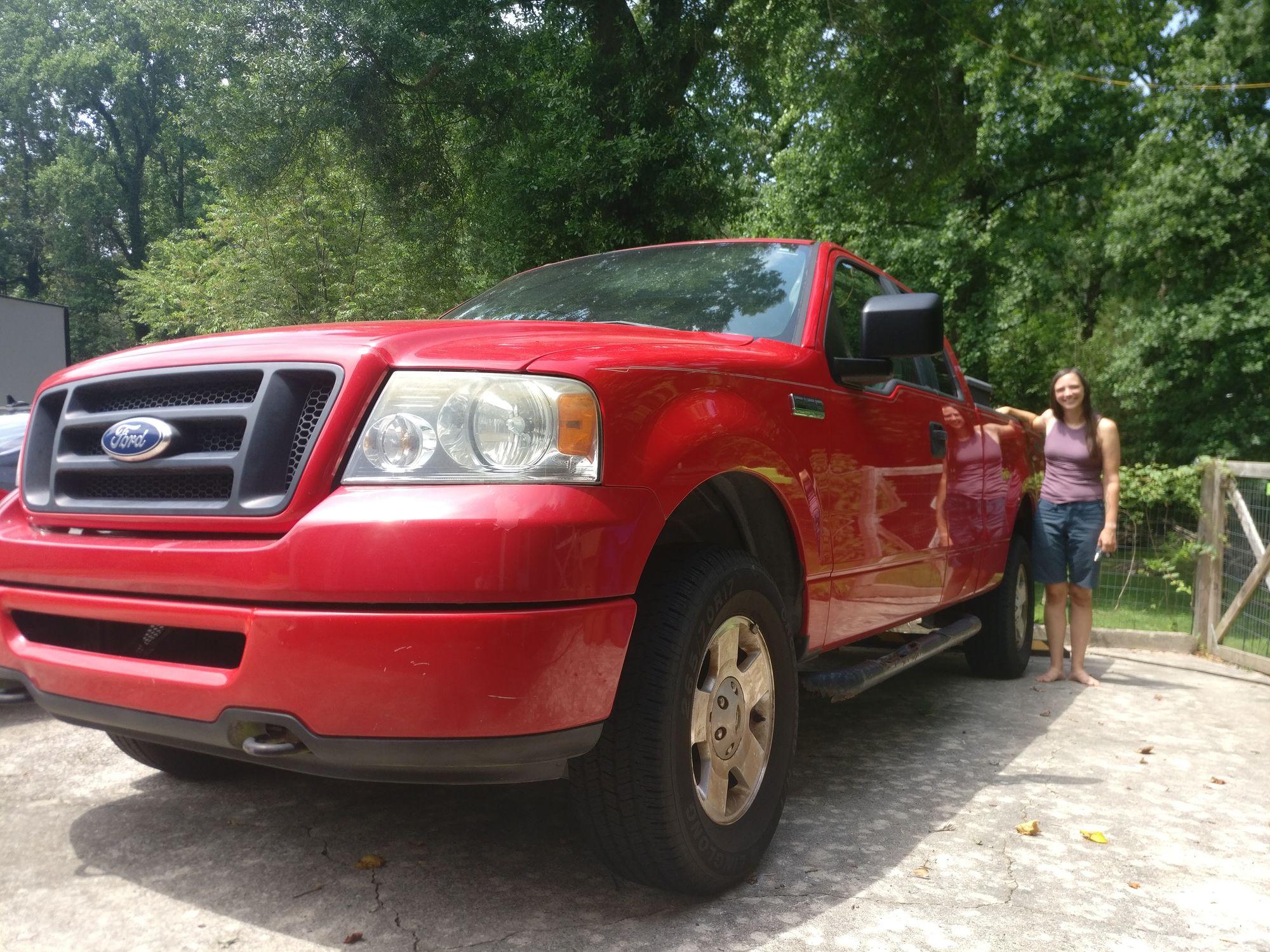
Ever since buying the bigger and heavier Winnebago Micro Minnie travel trailer, Autumn has been looking for a tow vehicle with a little more headroom in terms of towing capacity. However, most economists will tell you that the last 12 months have been the most difficult time to buy a used truck since the steel rations of WWII, what with the supply chain disruption constraining new supply, and the booming construction industry driving up demand and gobbling up old stock. So when a family friend said they would be selling their 2007 Ford F-150 STX Supercab 4x4, we felt we needed to snatch it up before it reached the open market.
I brought Clifford home for an inspection and extended test-drive in early May of 2022.
The mechanic's inspection found nothing fatally wrong with her (Clifford), just a few concerns typical for a truck of this age and mileage that did not require immediate attention and would be relatively inexpensive to address. With that, we knew the truck could satisfy our needs, and a few days later, papers were signed, money was exchanged, and Clifford legally became property of Autumn Welles.
This is not to say Clifford did not need any work. Quite the contrary. However, the work that she needed (in the near term) was not mechanical in nature, and could be completed by any number of out-of-work engineers for the cost of parts and materials, and, luckily, one such engineer "in between opportunities" happened to reside at the same location as Clifford. Which is how I, dear reader, come to be guest-authoring this blog post today.
Requirements and Initial Assessment
The attributes of a vehicle that can safely tow the intended travel trailer (2017 Winnebago Micro Minnie 1700BH) can be enumerated into the following list of requirements—some of which Clifford may have already satisfied:
- Towing capacity > 3800 lbs 🤷♂️
- Hitch weight capacity > 380 lbs 🤷♂️
- 7-pin trailer electrical connector ❌
- Trailer brake controller ❌
The towing and hitch weight capacity items above were assessed to be "sort of" satisfied. This model of F-150 comfortably exceeds the required parameters, but a decade of being parked within 500 ft of the intercoastal waterway had resulted in the accumulation of a concerning amount of rust on the existing hitch receiver.
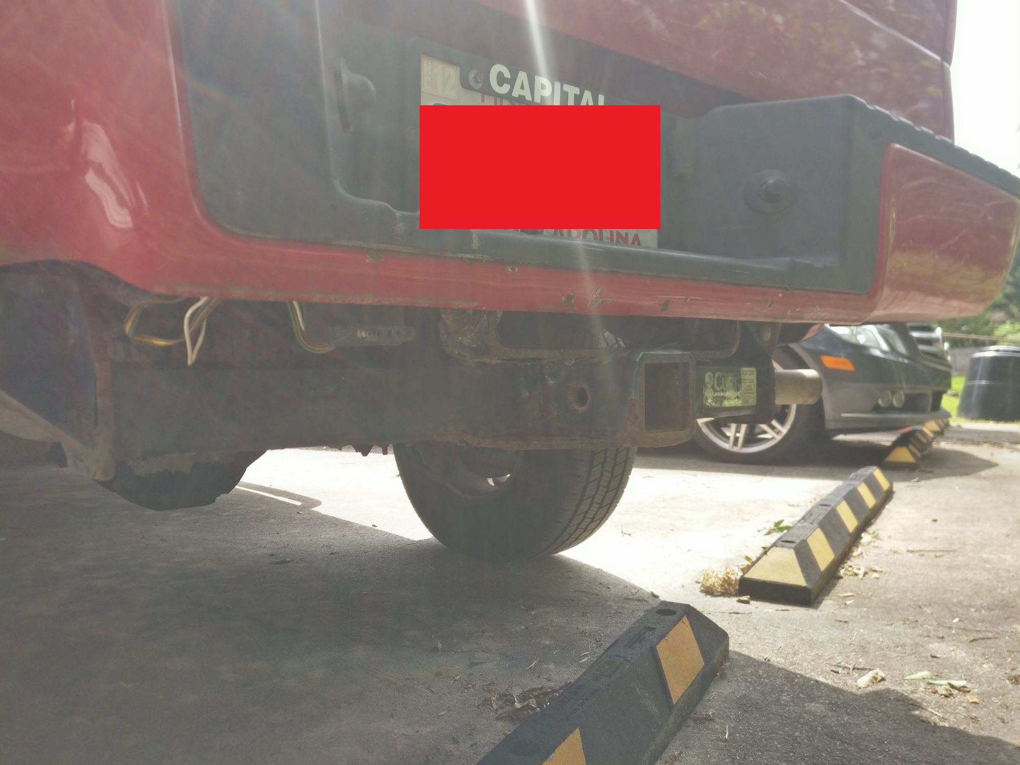
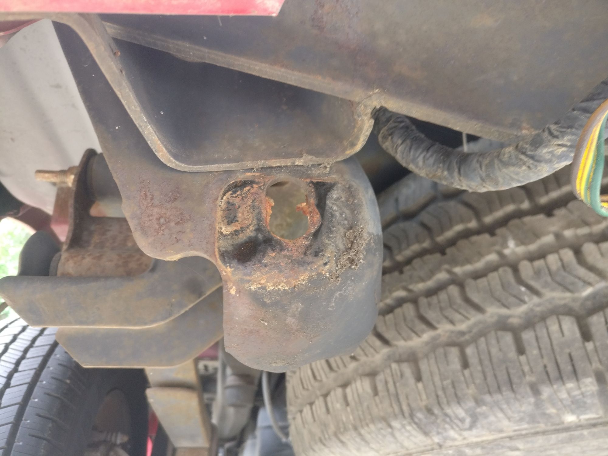
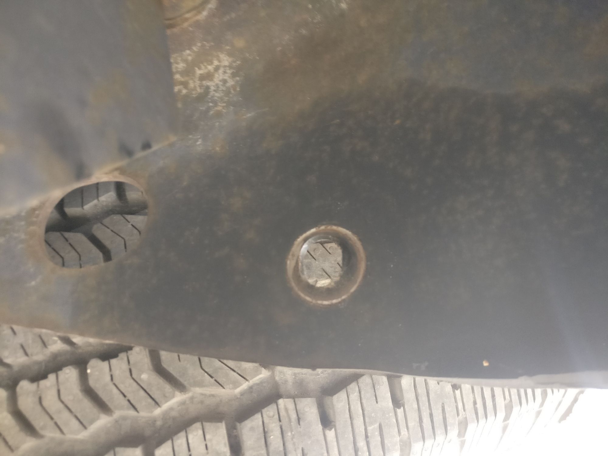
The above picture shows the 5-pin electrical connector (where a 7-pin connector is needed), and rust on the existing hitch receiver (this is the best picture I have from the pre-work, the rust was more significant that what might be seen here). Whether the rust had permeated the steel of the hitch receiver deeply enough to cause such significant strength degradation that a catastrophic mechanical failure posed a realistic risk is unknown. However, what is known is that such a mechanical failure (when hitting a bump on the highway at 70 mph) would be indeed catastrophic (and expensive), and the preventative remediation (replacing the hitch receiver) would be relatively cheap. So items 1 and 2 above are deemed unsatisfied for safety reasons.
Work Item Enumeration and Classification
The work items whose completion would result in the satisfaction of the above requirements can be classified into 2 categories: functionally required and health-and-safety concerns:
Functionally Required
- Install trailer brake controller
- Install 7-pin electrical connector
Health and and Safety Concerns
- Replace hitch receiver
- Replace running boards
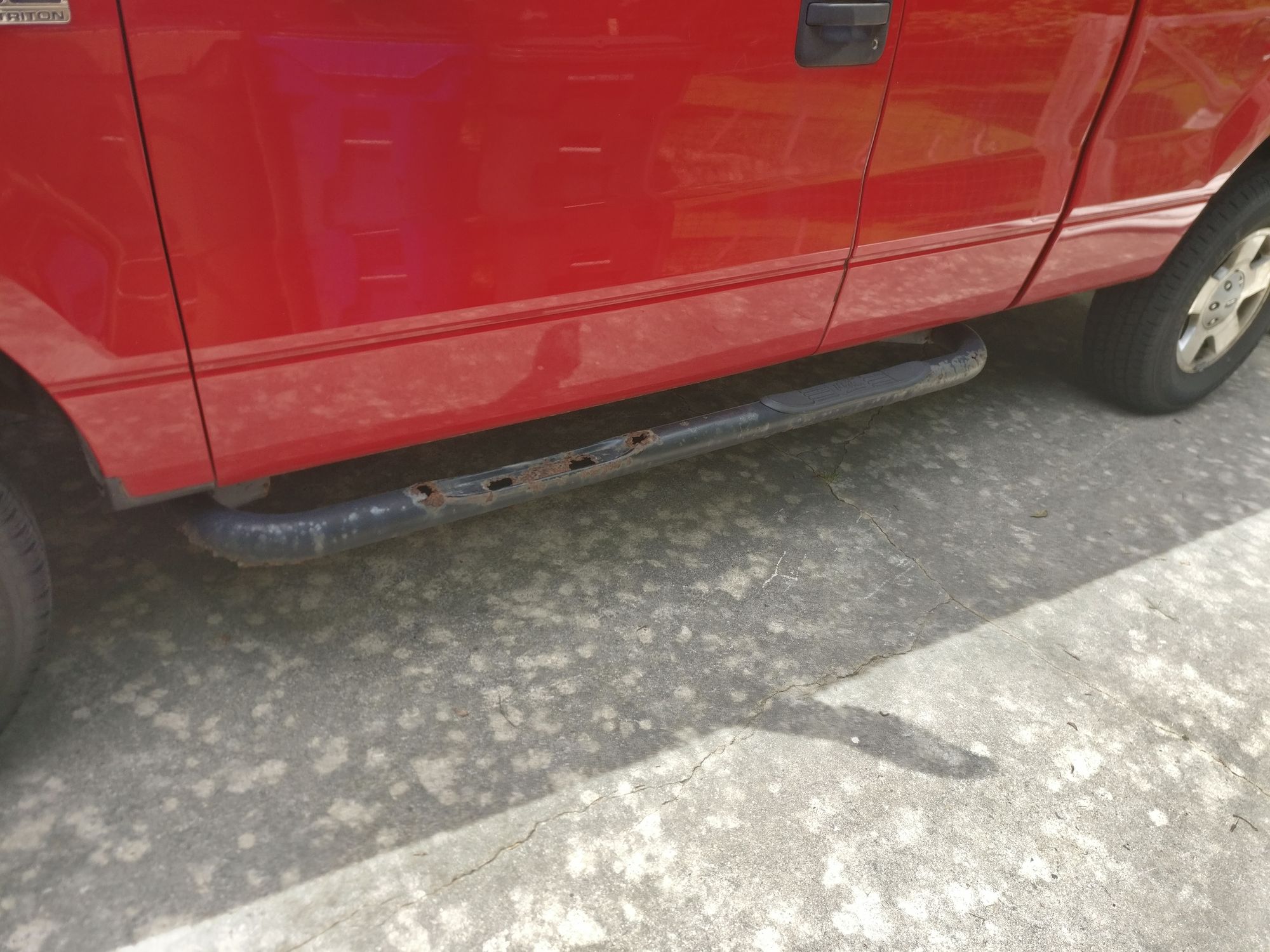
The running boards have hitherto been unmentioned, but they posed a safety risk of their own. Clifford's decade long tenure near the salty water of the intercoastal waterway had also resulted in rust here as well, so much so that the tubes were rusting though and the plastic pieces were falling off on the highway. It would only be a matter of time before someone (or some dog) cut themselves and became infected with tetanus. For this reason, their replacement (or at least removal) was classified and a health and safety work item.
Quality of Life Improvements
In addition to the imperative work items enumerated above, several quality-of-life and cosmetic improvements were identified whose completion might tie in nicely with the work already slated. These improvements are listed below:
- Replace stereo head unit
- Install reverse backup camera
- Install rear seat dog protection (for Gambit and Loki)
- Install front center dog seat (for Jean)
- Install tailgate pad (for bikes)
- Replace floor mats
Component Selection
With the requirements well defined, we were ready to research, identify, and procure components that would satisfy those requirements. Below is what we came up with:
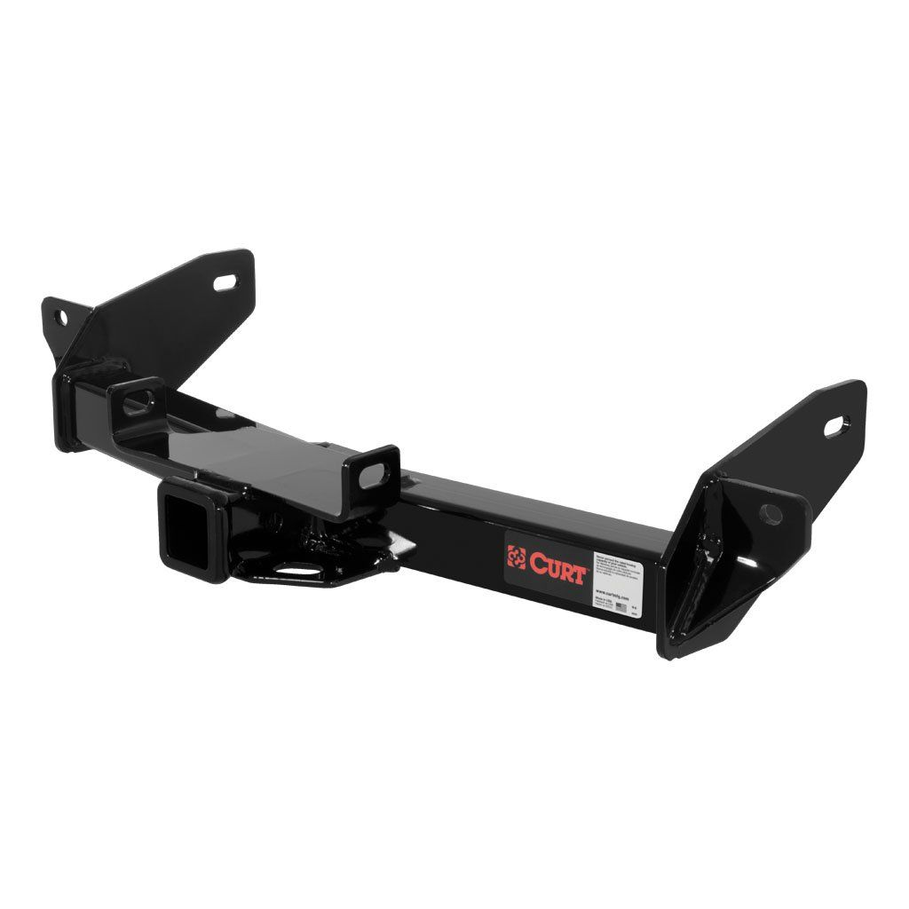
Hitch Receiver
Curt is the ubiquitous brand for towing hardware, so was naturally the first place we looked. We settled on their class 3 #13360.
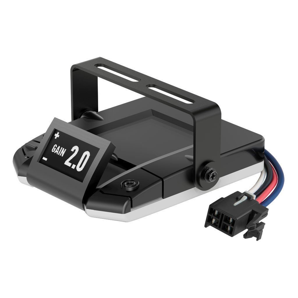
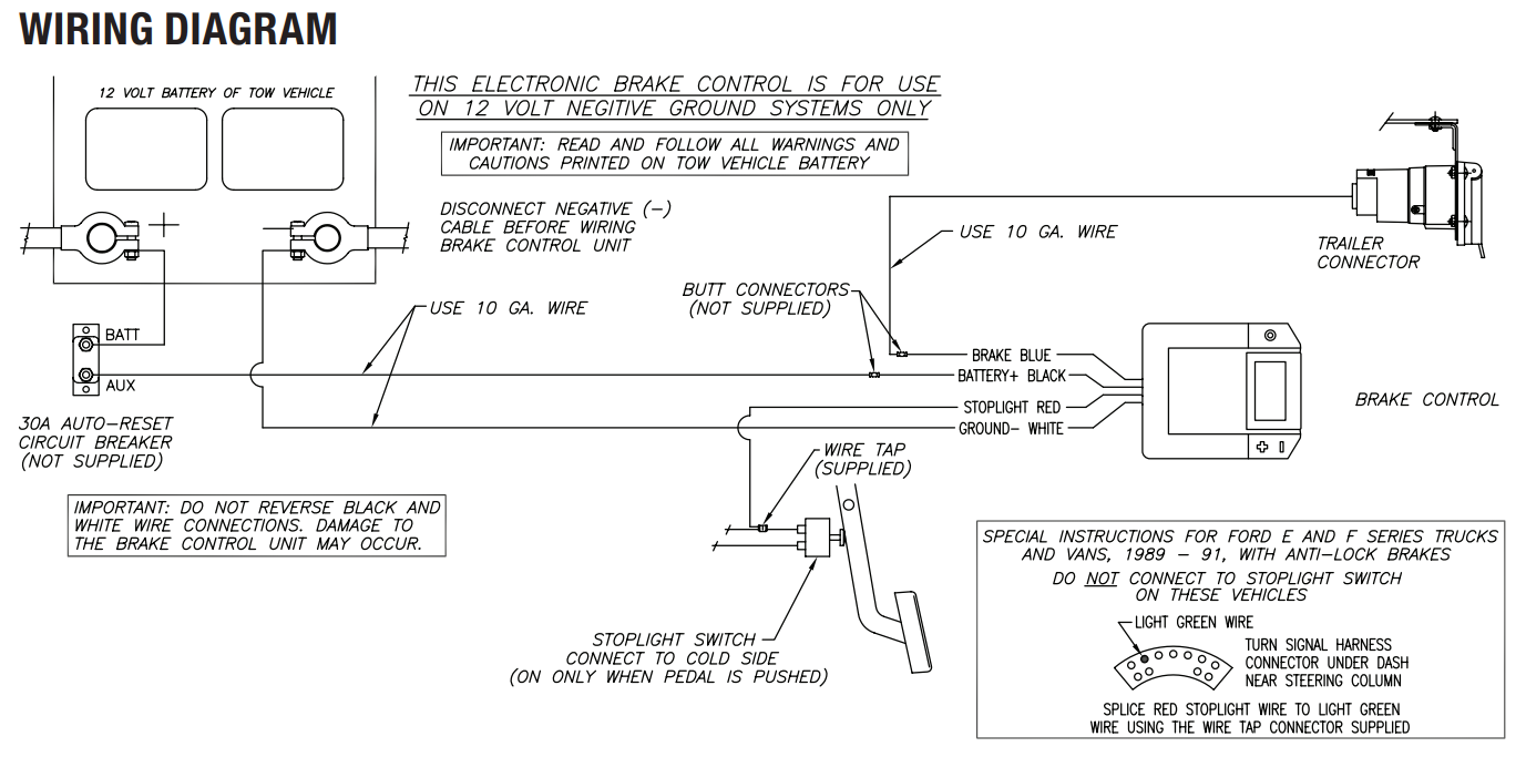
Trailer Brake Controller
We decided to trust Curt with our towing electronics as well, and went with their #51160 controller (and accompanying #51515 wiring harness).
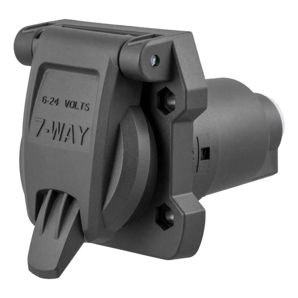
7-Pin Trailer Electrical Connector
Continuing our trust with Curt, we selected their #58155 heavy duty socket and related mounting hardware (#58510 & #57202) to strap it to the hitch receiver.
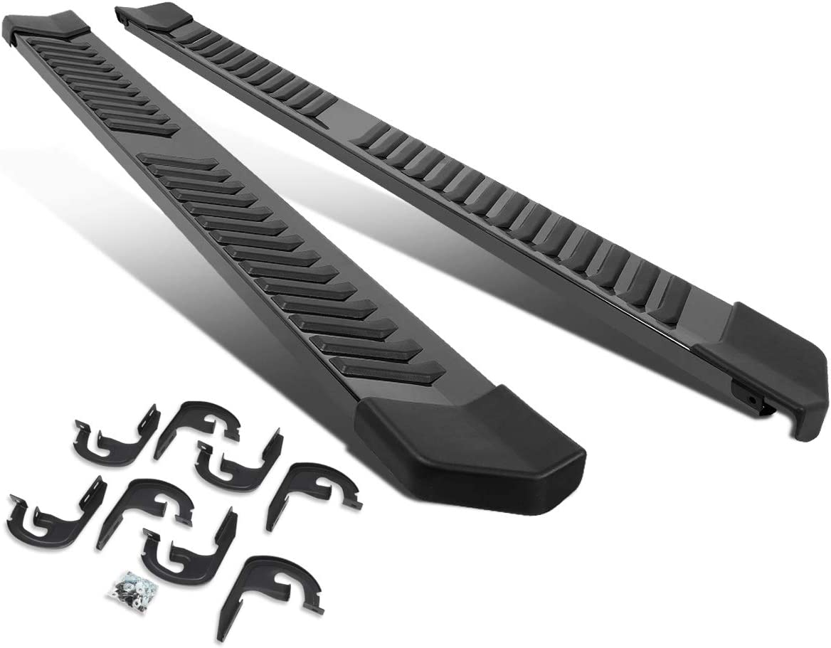
Running Boards
Autumn looked on Amazon and found these simple, stylish, and effective running boards.
Stereo Head Unit
We knew we wanted a unit that would satisfy its own set of requirements:
- Touch screen
- Backup camera input
- Wireless Apple Carplay
- Wireless Android Auto
- Hard volume controls (preferred)
The supply chain disruption has made commodity electronics hard to get and consumer electronics expensive, but the Jensen 710W satisfied all our requirements at a palatable price.
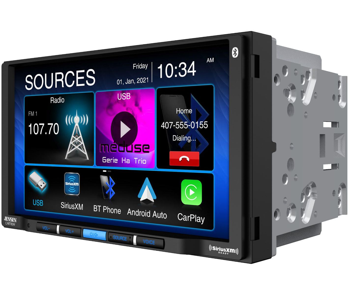
This model is difficult to recommend to everyone, however, owing to its lack of support for the Radio Data System and HD Radio and only supporting satellite radio up to SiriusXM 2.0. We were willing to swallow these deficiencies since we would primarily use Carplay, Android Auto, or Bluetooth Audio; occasionally use FM radio; and never use satellite radio.
Backup Camera
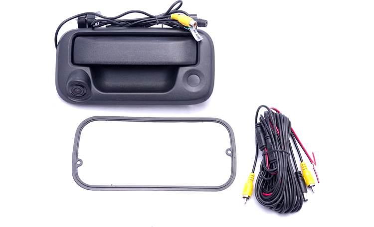
Crutchfield led us to the Crux CFD-03 backup camera that would stylishly replace the original tailgate latch handle.
I was already getting exciting thinking about using the backup camera to line up the hitch ball with the trailer coupler.
Wiring Planning
With our components picked out, it was now time to look at their I/Os and installation documentation and draw up a wiring diagram.
Brake Controller
Curt provided the below diagram in their installation instructions.
7-Pin Trailer Electrical Connector
Wikipedia provided some useful information on this topic. Below are the required connections for the SAE J2863 7-Pin trailer electrical connector.
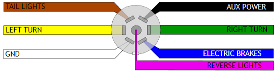
And below is what already provided by the existing 5-pin flat connector and was available for reuse.

As you can see, the 2 new lines are for electric brakes and aux power. These are the lines we'll be running later. The ground on the 5-pin would be discarded and replaced with a larger gauge one.
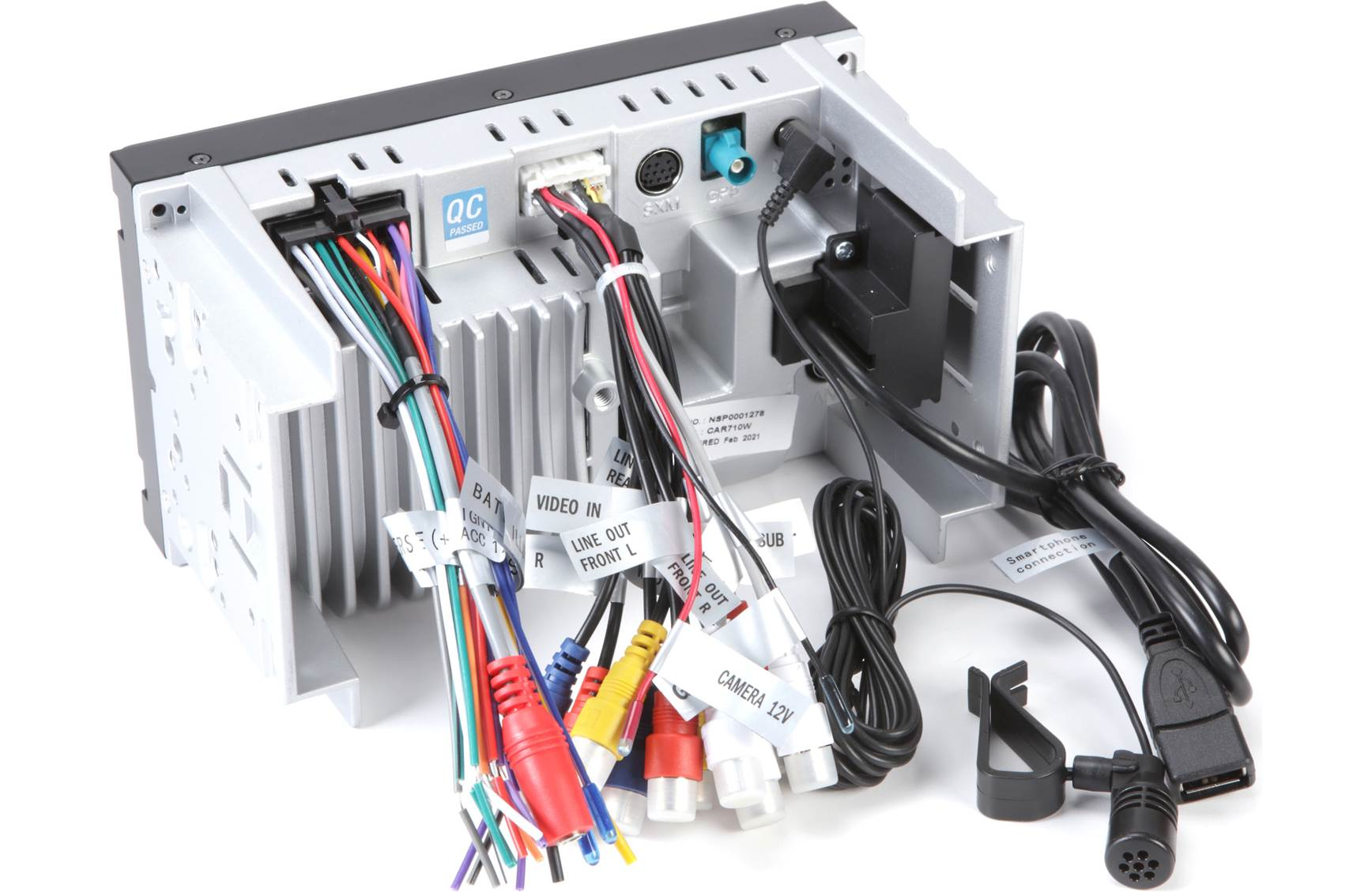
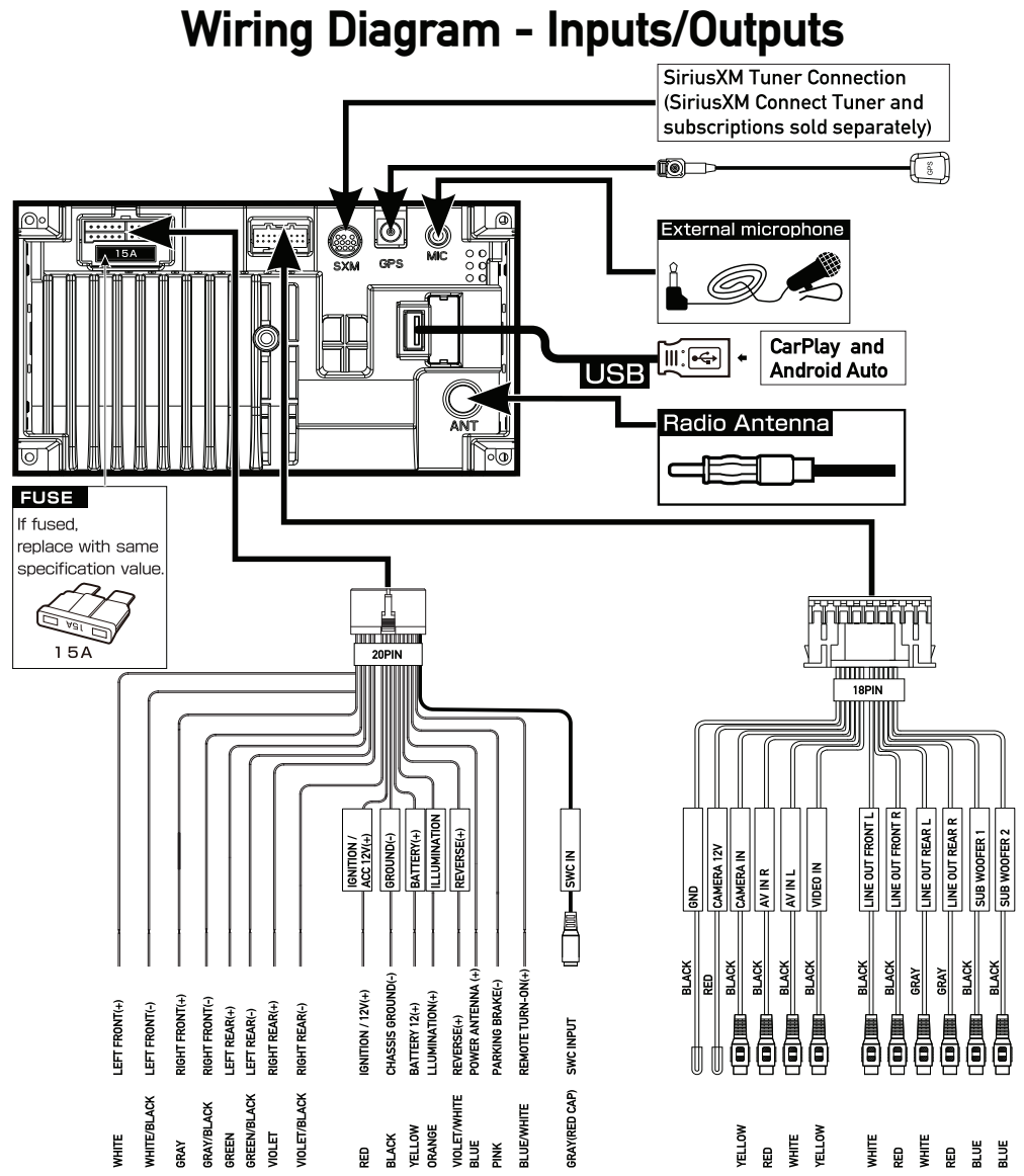
Stereo Head Unit
Below is the Input/Outputs diagram provided by Jensen for their 710W.
Backup Camera
I couldn't find a good, accurate wiring diagram of the backup camera, but here is a picture that better shows some of the connections.
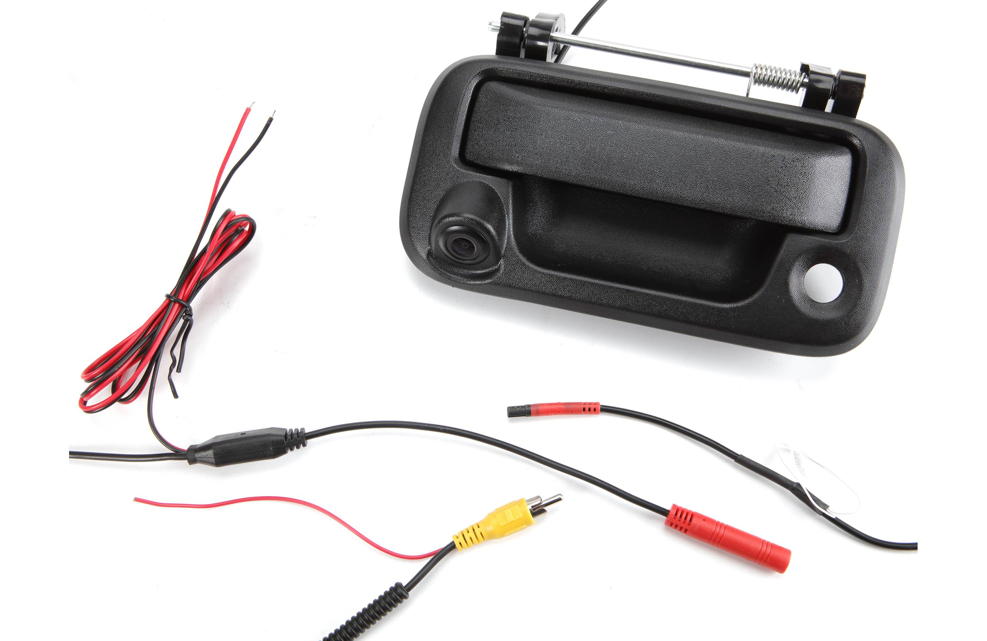
The yellow RCA plugs into the head unit. The camera is powered by either the red wire that rides with the RCA or by the other red wire somewhere near the rear of the vehicle. The black wire should be grounded to the frame.
Wiring Diagram
With all these inputs and outputs taken into consideration, it was time to draw a wiring diagram. This is what I came up with.
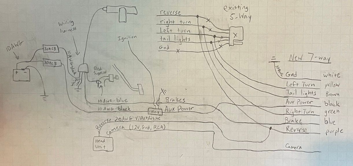
This was the original plan, but there ended up being some implementation deviations that I will enumerate here:
- The original plan was to run a new line from the reverse light to the reverse input of the head unit and to use the 12V provided by the head unit to power the camera. I ended up powering the camera directly from the reverse lights and also using that to signal to the receiver's reverse input via the RCA's red rider. That way, I ended up not having to run another line for the reverse signal. This is in contradiction to the camera's documentation, which said to power the camera at one of the terminals and isolate the other, but I don't see the harm in using the "isolated" terminal to signal the head unit.
- There is a relay to enable voltage to the 7-pin connector's aux power line when the ignition is on. In the diagram the source of the ignition signal is not specified. I ended up splicing into the ignition signal going into the stereo head unit.
- The stereo head unit has an input for parking brake to enable video playback. This is not pictured here, but I did end up tapping into the parking brake switch to enable this functionality.
Exterior Work
With all the parts in hand and some semblance of a plan on paper, it was time to get to work.
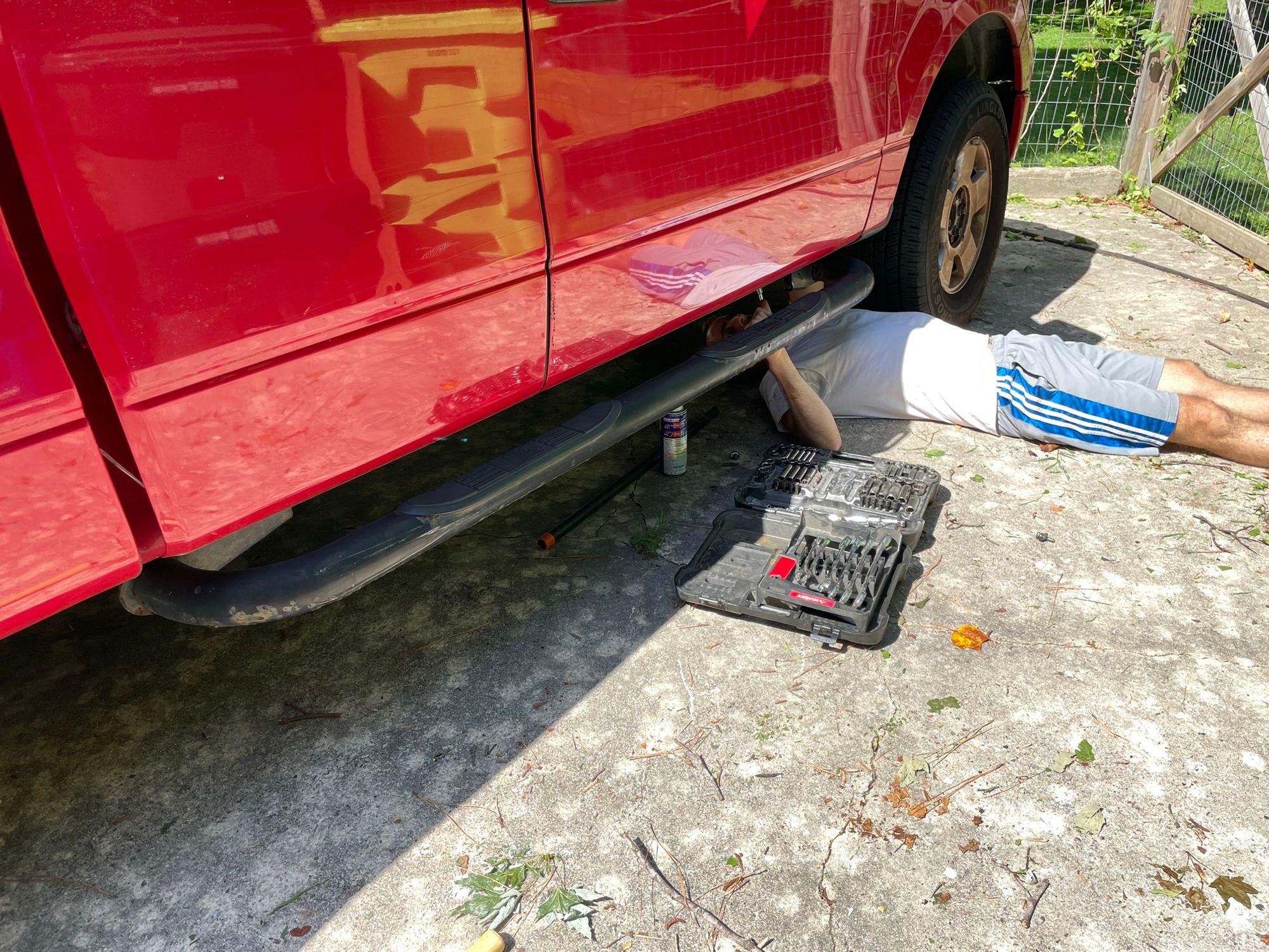
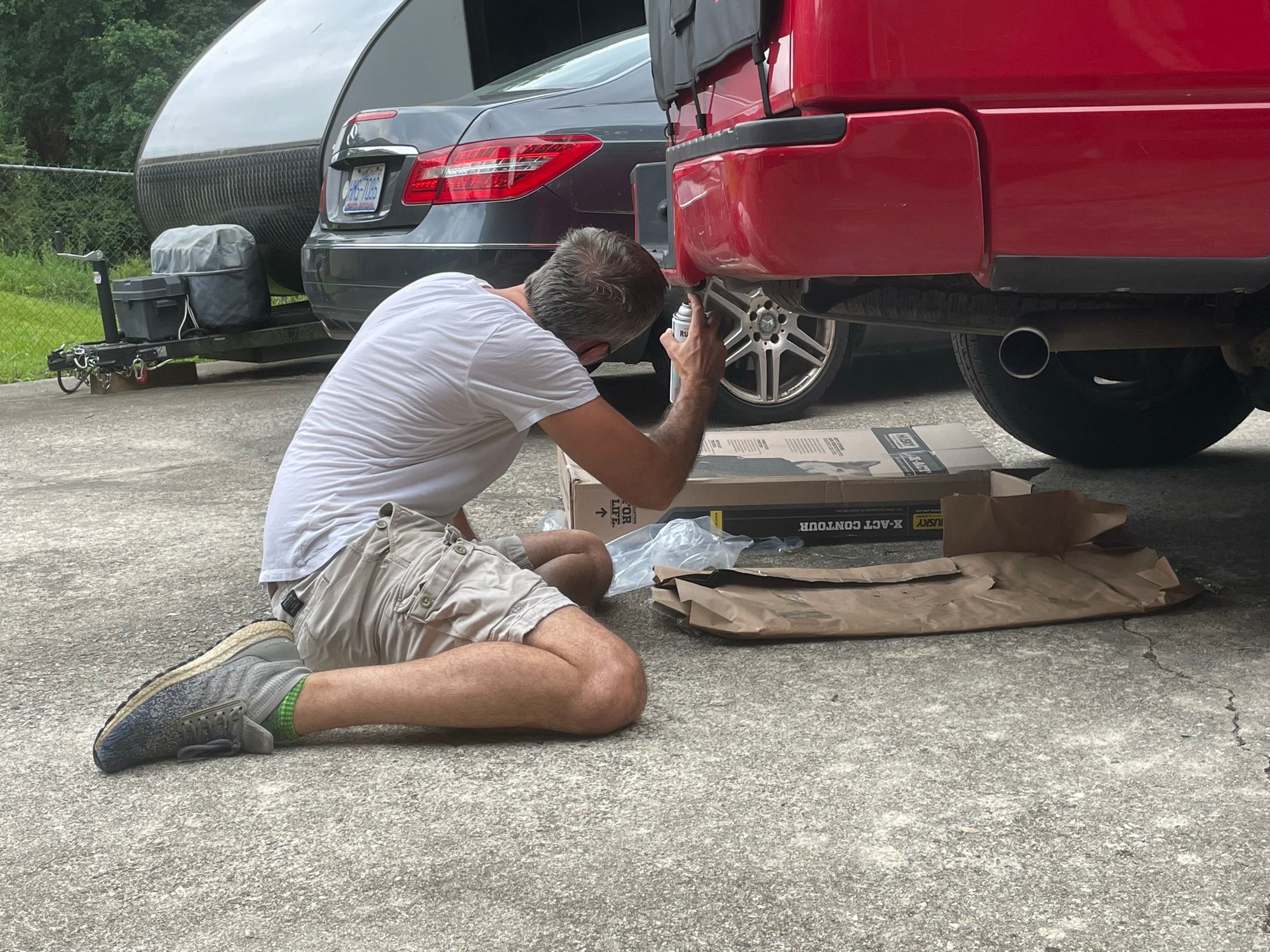
Remove Old Rusty Running Boards
Here I am taking off the old running boards. This was done first so I would have more room to crawl around under the truck.
We don't have any pictures of the truck without running boards, but it looks strangely "lifted".
Hitch Receiver
Next was was the hitch receiver. Since the new 7-pin connector would be strapped to it, it made sense to get this part in place to support the later electrical work. Below are some pictures of the connection points once the old receiver was removed.
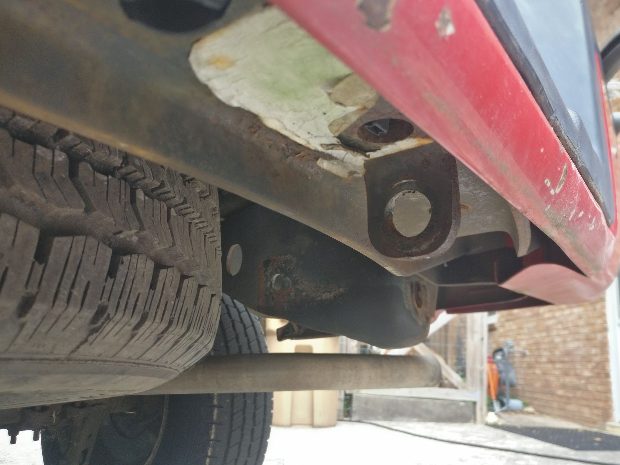
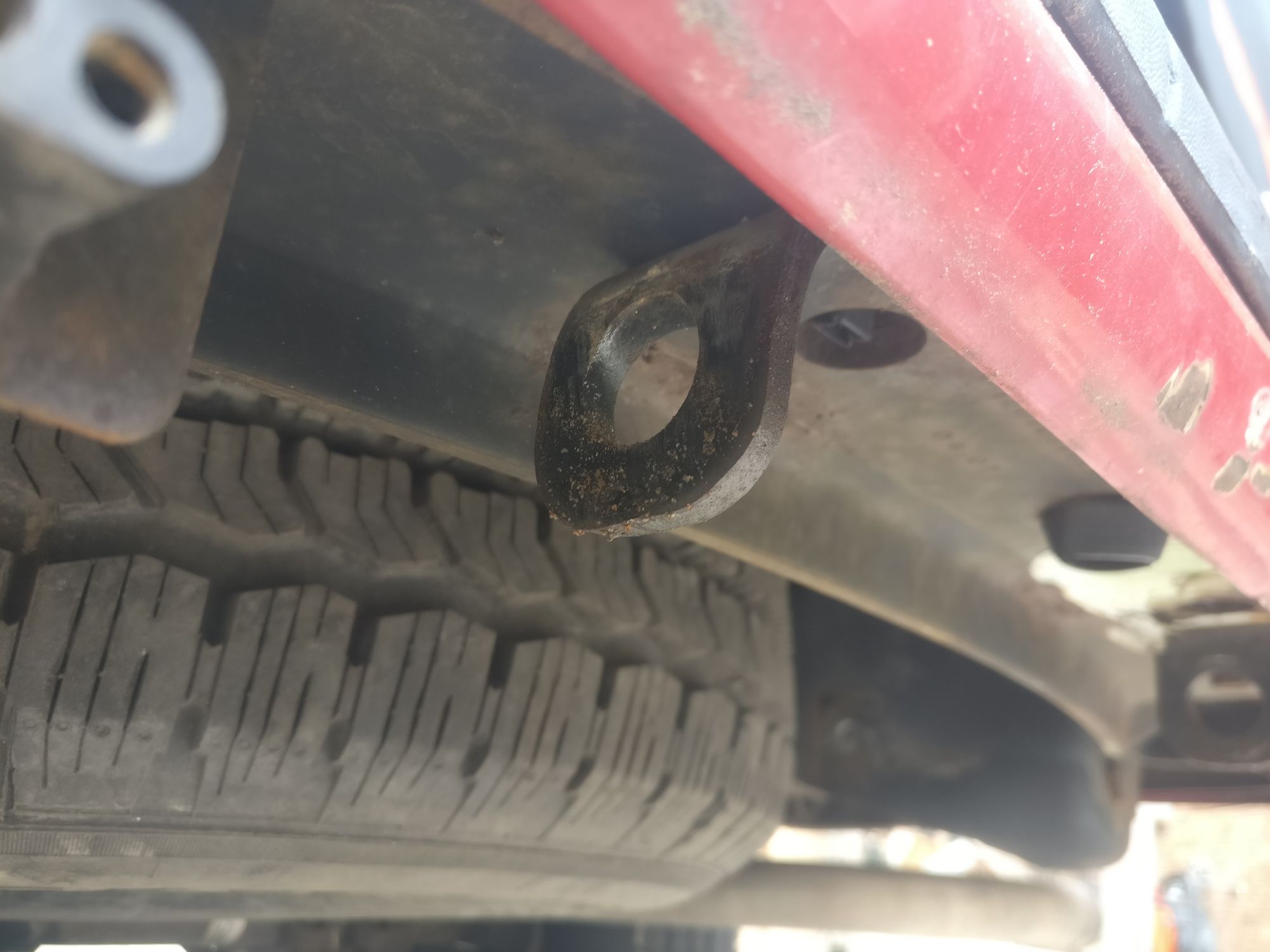
Relievedly, the frame steel was in much better condition than the old hitch receiver. I used a wire brush to scrape off as much rust as I could and went over the points of contact with a coat of rustoleum.
We then installed the new hitch receiver but do not have any pictures during this stage of work.
Electrical and Wiring
Backup Camera
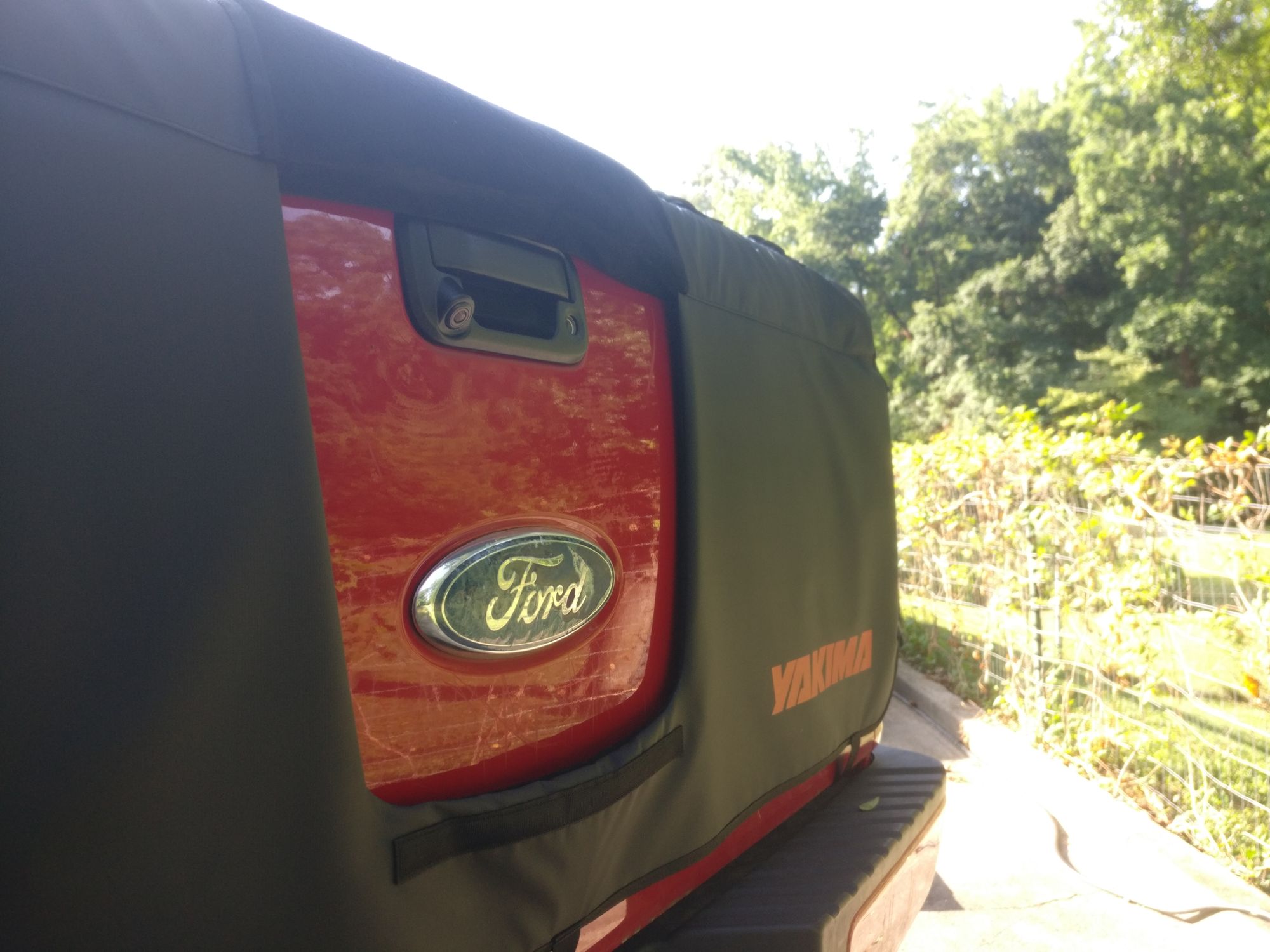
The backup camera was the cheapest and simplest piece of hardware, so I decided to install that first. Below is a picture of the installed camera (and the tailgate pad). It looks just like a normal tailgate latch handle, but with a little camera.
Power Distribution
The wiring diagram calls for two 30 Amp auto resetting circuit breakers - one for the brake controller and one for the trailer aux power. The trailer aux power also has an inline relay to enable voltage only when the ignition is on. Below is a picture of the 2 circuit breakers and the relay at an intermediate stage of work. It's tucked inside the dash in an empty space above the glove compartment.
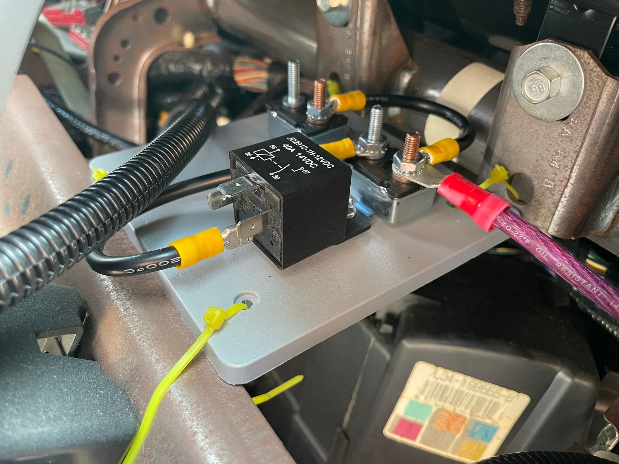
I use 8 AWG to go from the battery to the aux power circuit breaker and 10 AWG to the relay and to daisy chain to the brake controller circuit breaker. The potential for 60 Amps untripped is above advisable for 8 AWG copper, but if the trailer aux power and brake controller are simultaneously pulling 30 Amps, something else has gone wrong.
Stereo Head Unit Harness
Unpictured in the wiring diagram is the wiring harness between the new stereo head unit and the truck's existing connector. It is pictured below.
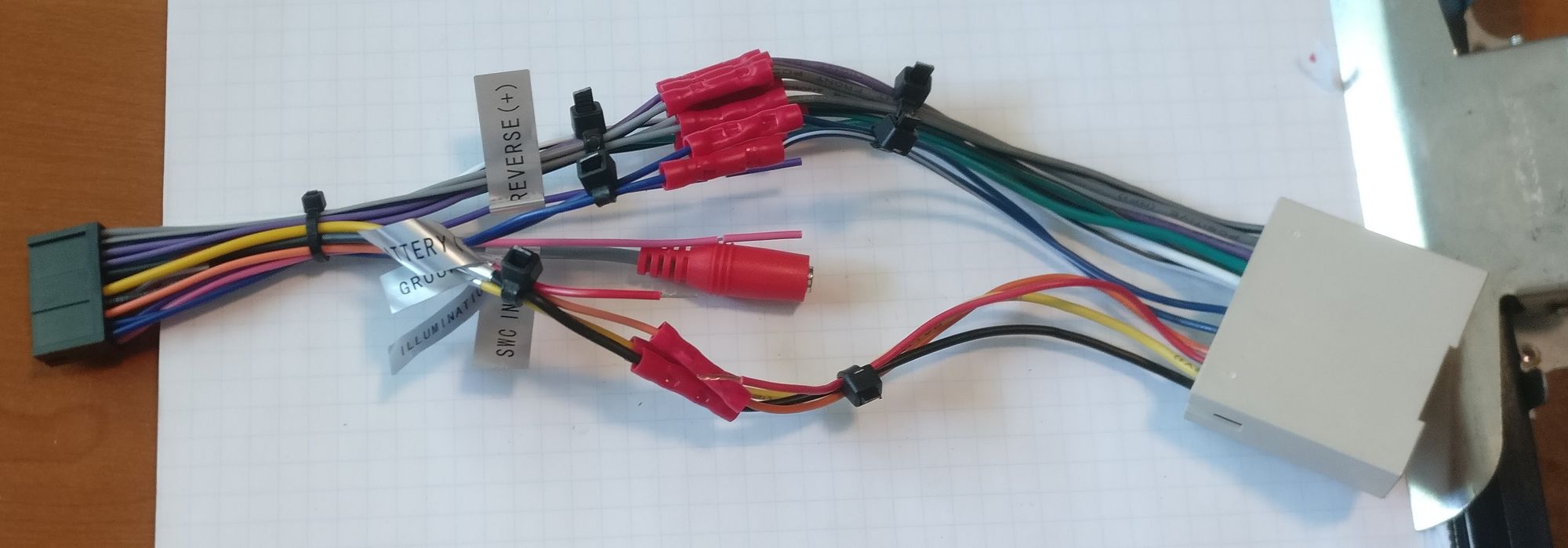
This is all typical radio stuff (power, ground, dash light, speakers). The ignition splice, camera feed, and reverse signal will be connected later.
Brake Controller
There's a little space below the AC controls that seems to be made for a brake controller in my opinion.
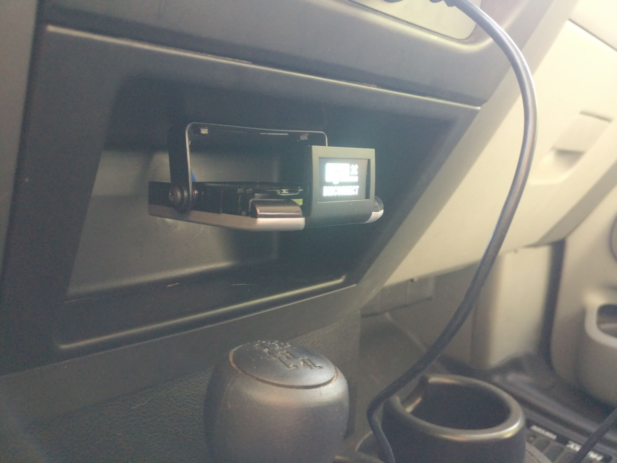
I took out this piece of plastic, mounted the brake controller to it, and punched a hole to feed the wires up into the dash. The wires and hole are occluded by the bracket.
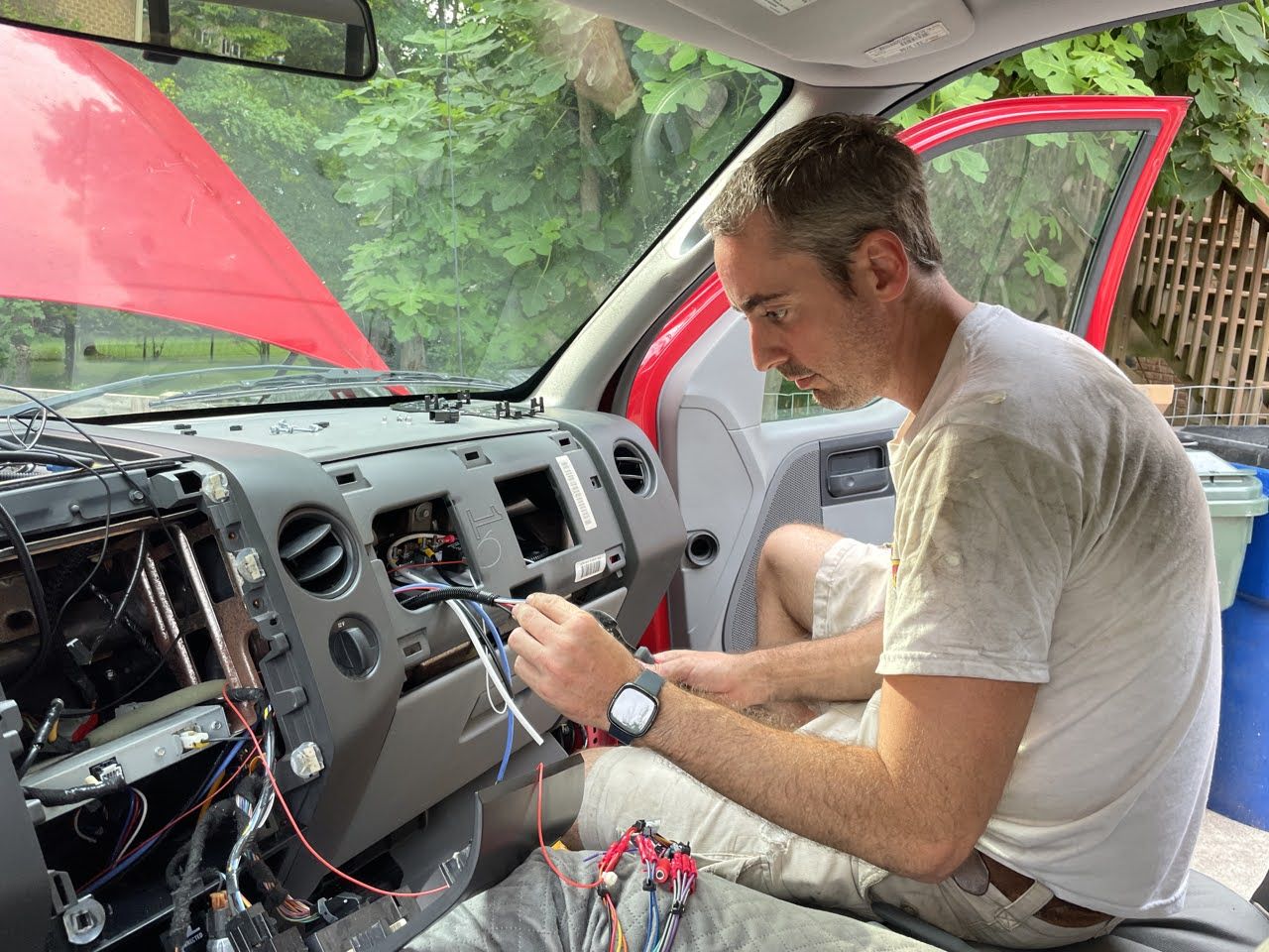
Dash Connections
With the backup camera, power distribution, radio harness, and brake controller in place, it was time to wire everything together like in the diagram and connect up the 7-pin controller too. Below is a picture of the dashboard mostly taken apart. If you squint, you can almost see the power distribution board inside the dash above the glove compartment.
I ran the new aux power and brake lines to the driver side of the dash, down to the floor, below the door trim, out a wire access hole, and then followed some existing wire paths to the location of the new 7-pin connector.
I then ran the camera line down through the tailgate, through an access hole, under the bed, and met up with the new aux power and brake lines. From there, I ran the camera line along the same path I used for them back to the center of the dash where it could access the stereo head unit.
This finalized the connections to the brake controller.
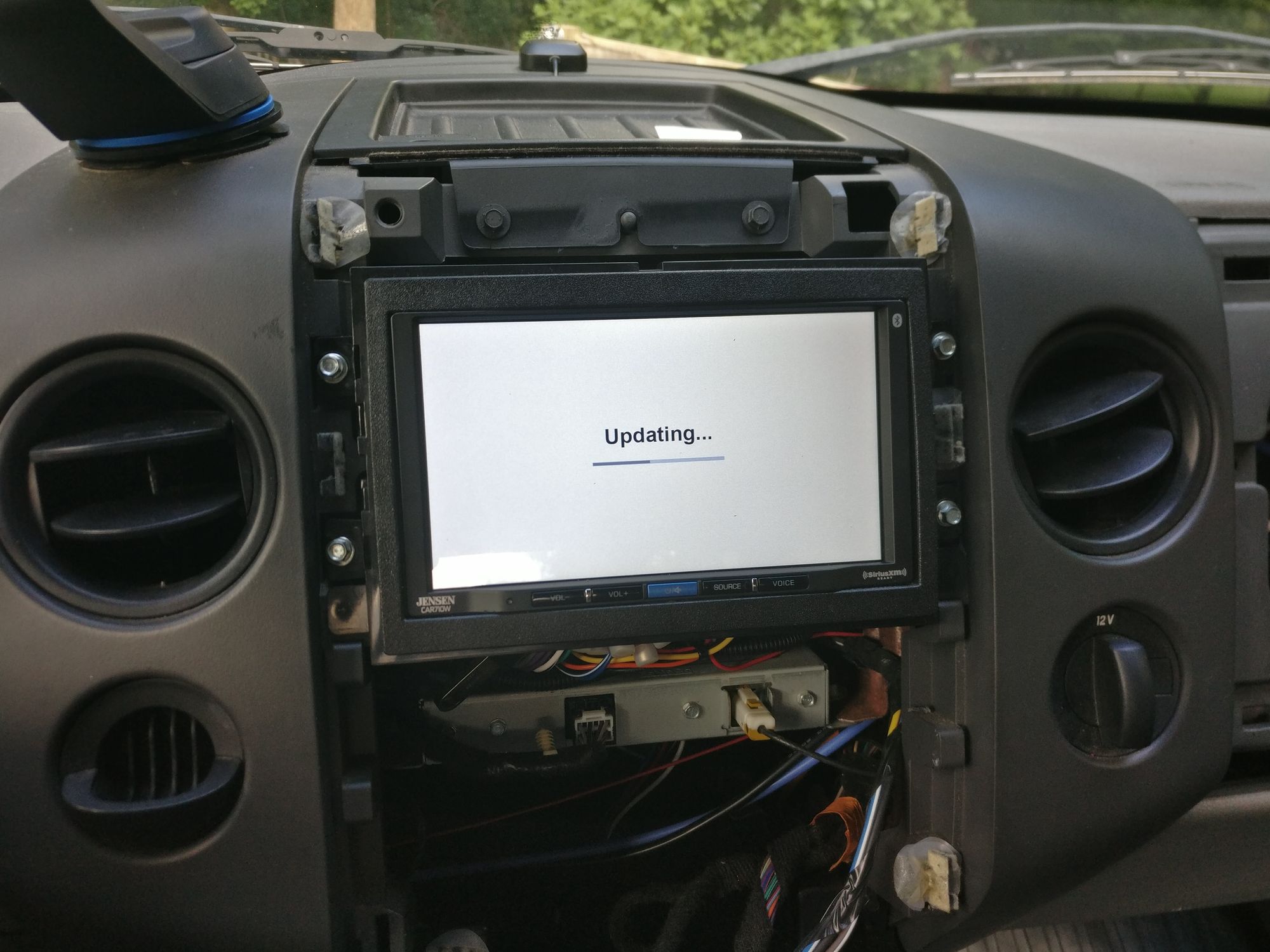
Stereo Head Unit
With all the wires in place it was time to install the stereo head unit (and update the firmware of course).
7-Pin Trailer Electrical Connector
With the front-of-vehicle wiring done, next was the termination at the rear-of-vehicle connector. Below is a picture of the new 7-pin connector strap-mounted to the new hitch receiver (and my tidy wiring work).
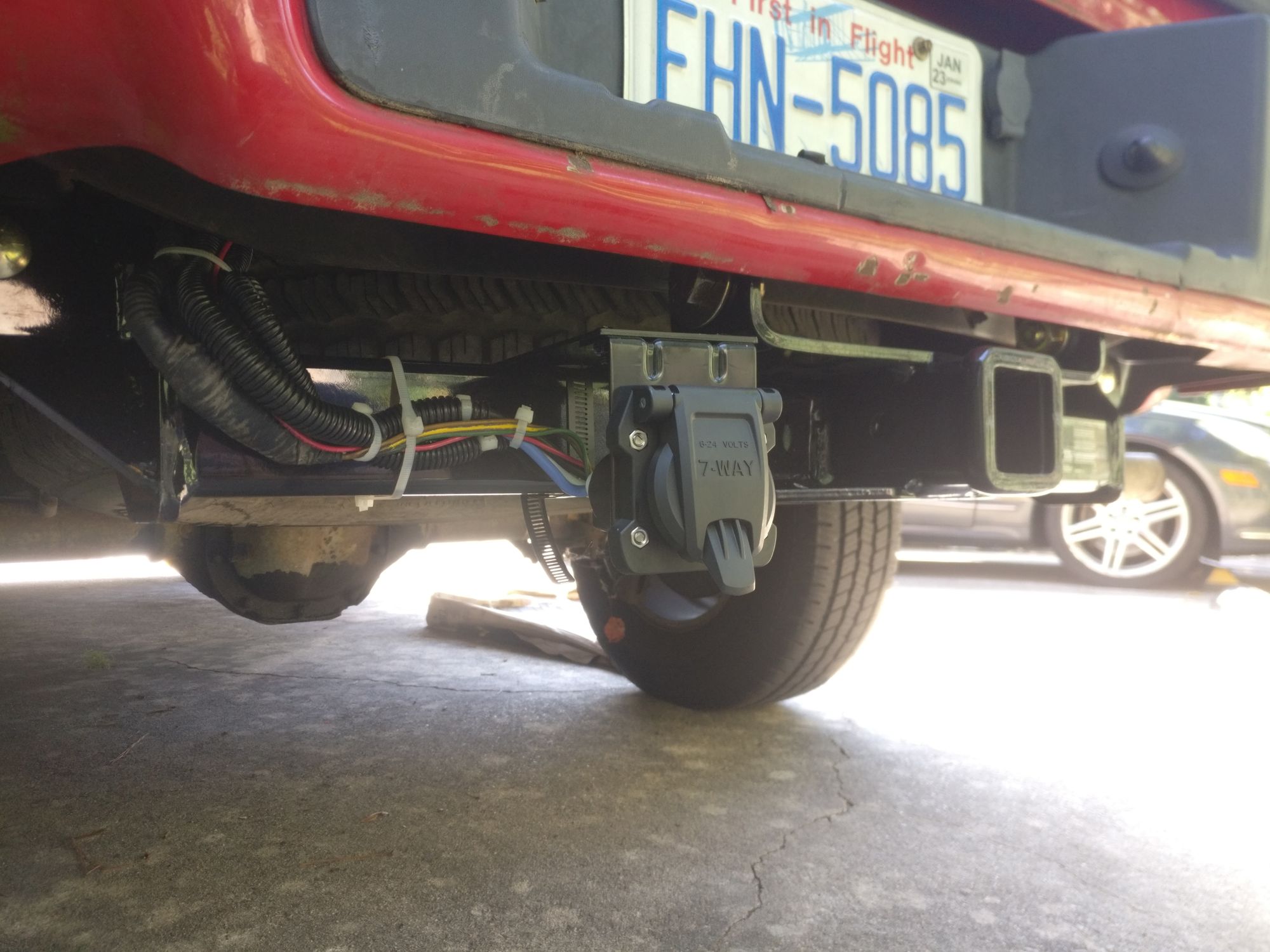
As I mentioned earlier, the existing ground from the old 5-pin connector was snipped short and discarded, and a new 10 AWG ground was run to an existing grounding point on the frame.
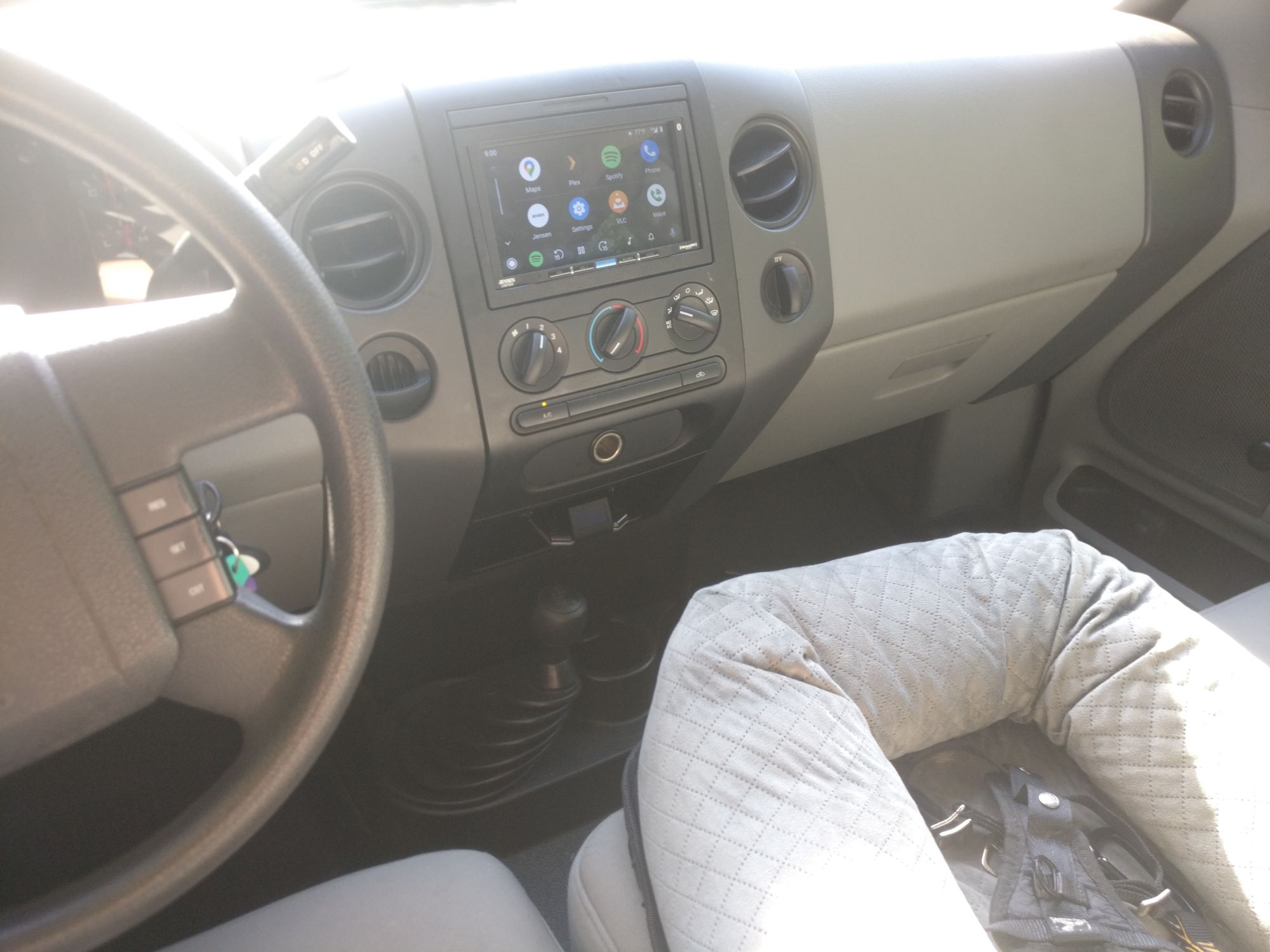
Buttoning up the Interior
Below is a picture of the reassembled dashboard. The new stereo head unit is showing the wireless Android Auto interface, and the trailer brake controller is visible just above below the cigarette lighter power outlet. You could never tell there's a horrid rat's nest of amateur electrical work just behind the dash.
It's worth noting that many steps and implementation details have been omitted for the sake of brevity.
More Exterior Work and Niceties
With all the electrical work done, it was time to install the new running boards and other quality of life improvers.
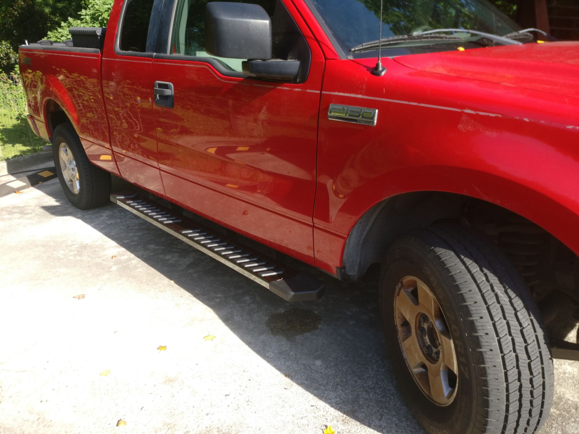
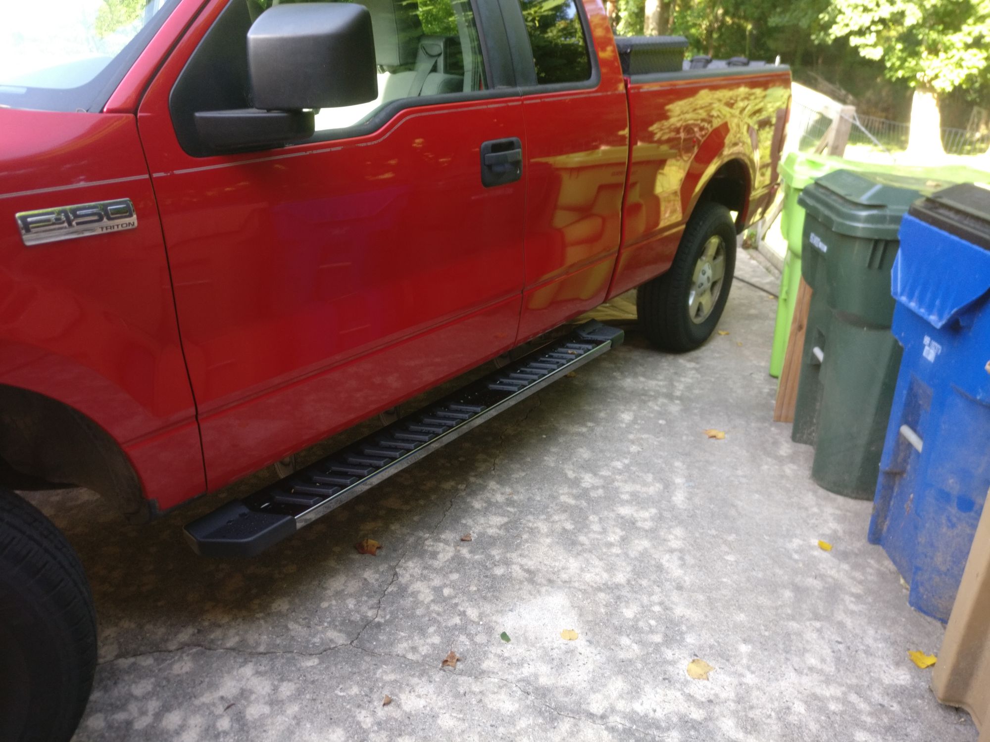
Running Boards
Below are a couple pictures of the new running boards.
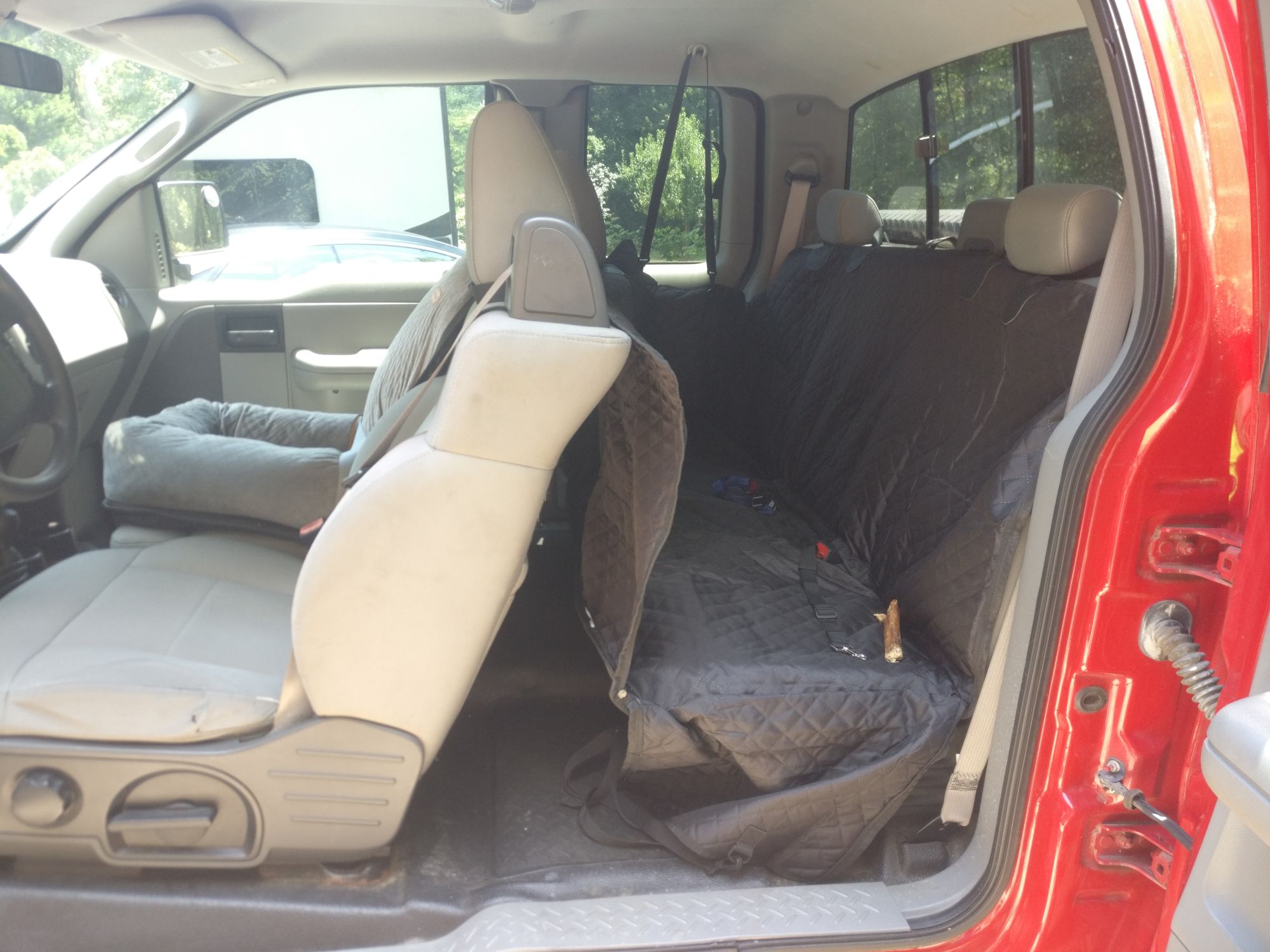
Rear Seat Protector
Below is a picture of the hammock to protect the rear seat from Gambit and Loki.
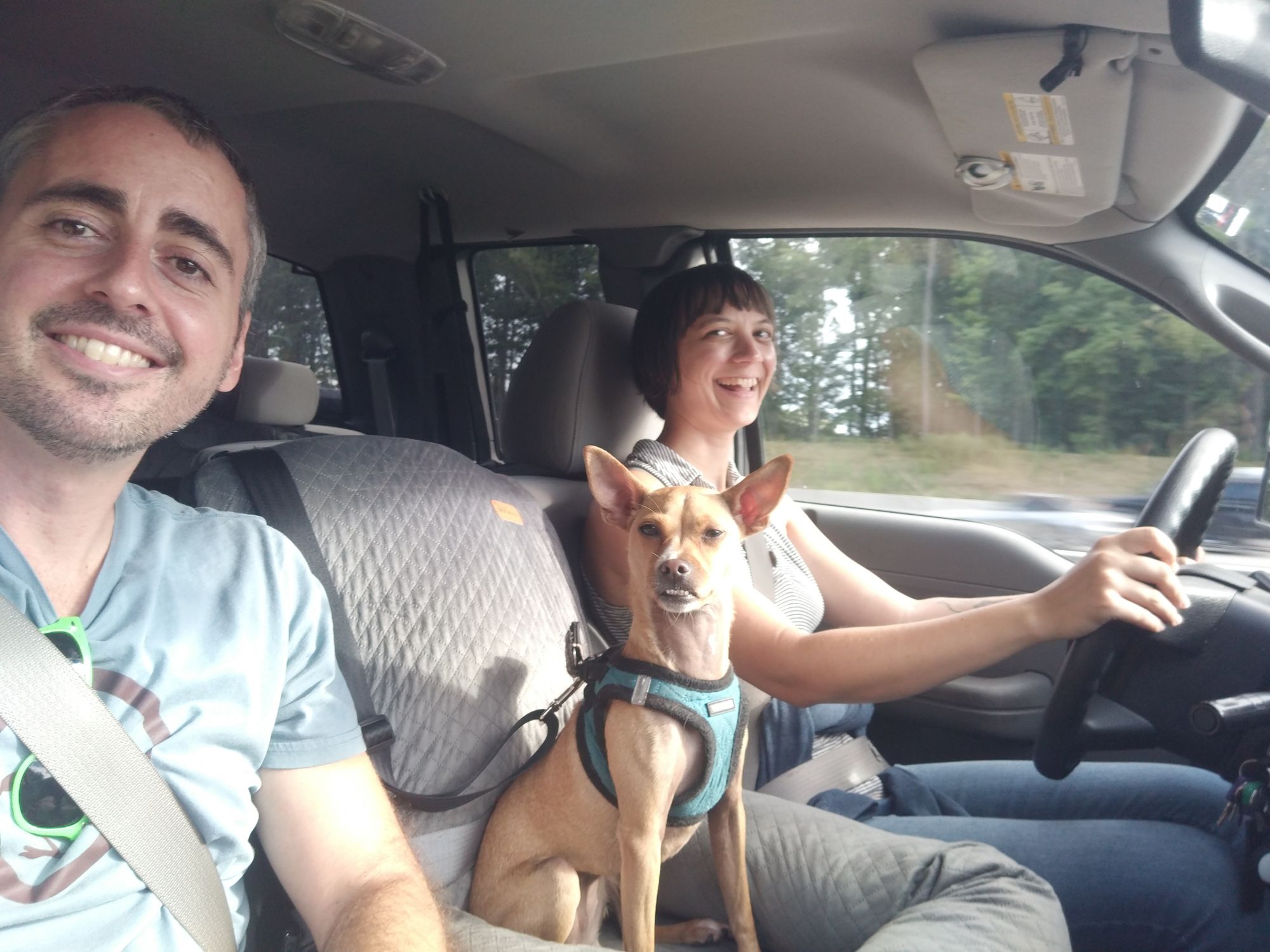
Jean's Seat
Below is a picture of Jean riding in her new seat.
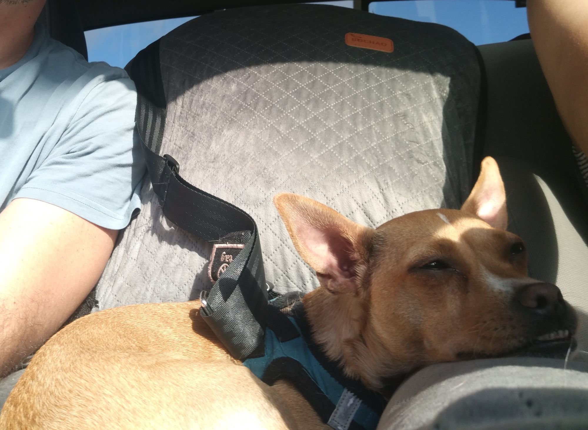
And here's one of her almost sleeping in her new seat.
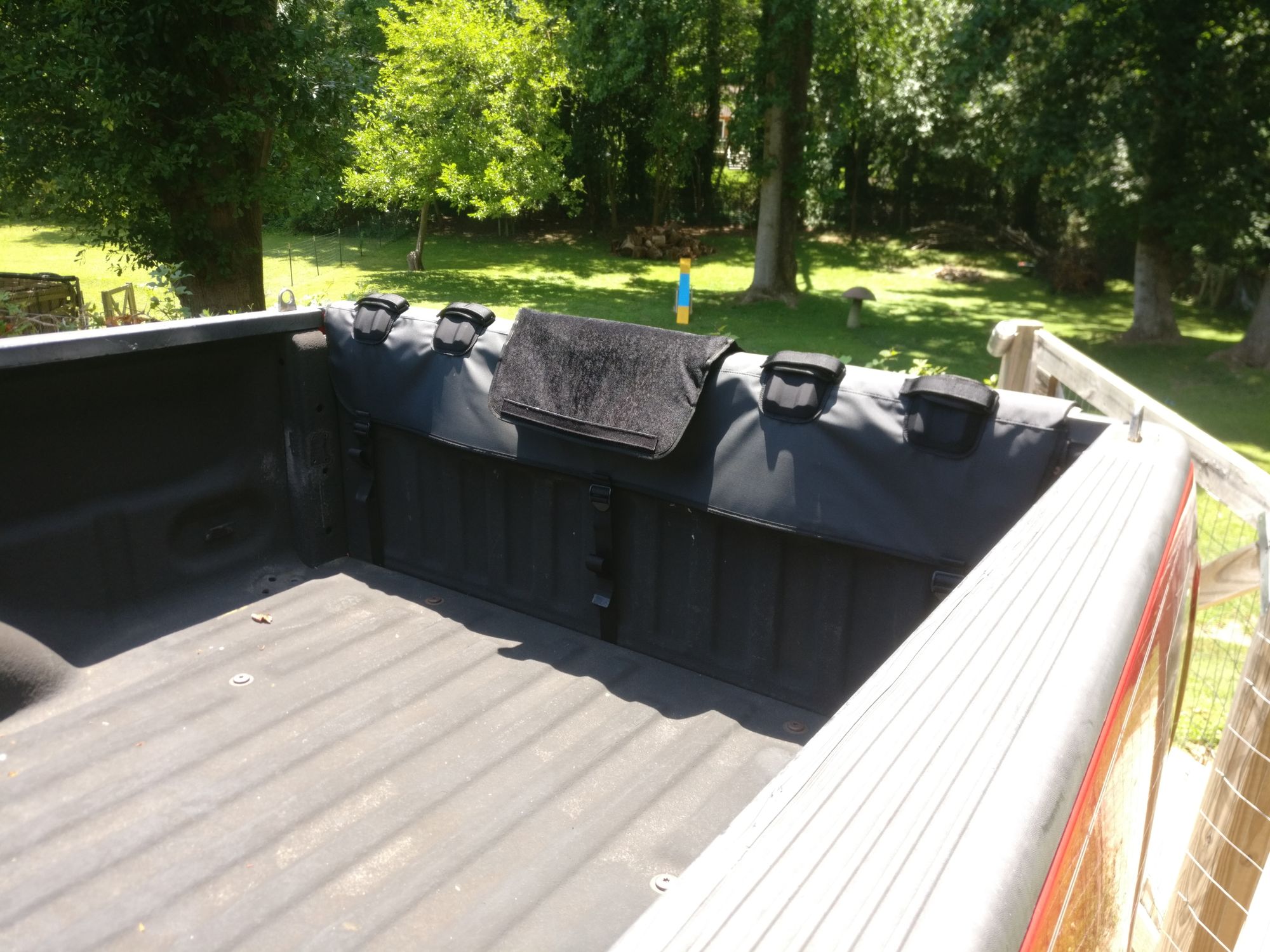
Bike Tailgate Pad
Below is a picture of the tailgate pad for carrying up to 6 bikes.
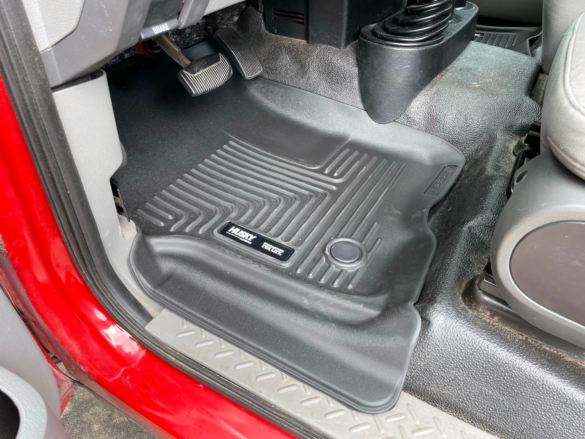
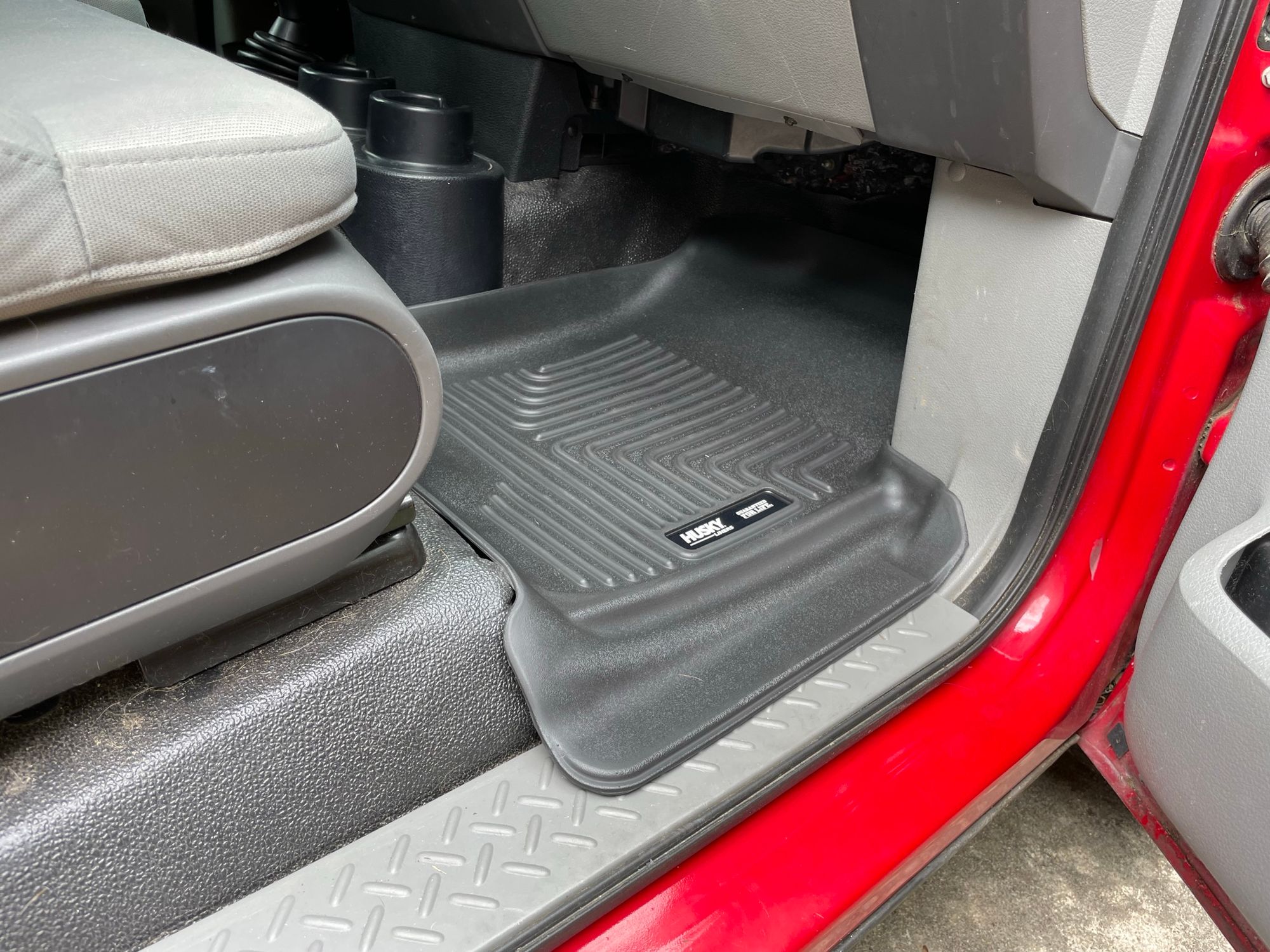
Floormats
Below are some pictures of the new floor mats.
Final Thoughts
After about a week of work, it feels like we have a new truck. The modern head unit displays snappy navigation instructions, and the new floor mats provide that new car squeakiness and smell. The real test will be tomorrow, when we hook up a trailer for the first time and assess the functionality of that trailer's lights and brakes as provided by the new 7-pin connector and associated wiring and electronics. Fingers crossed!
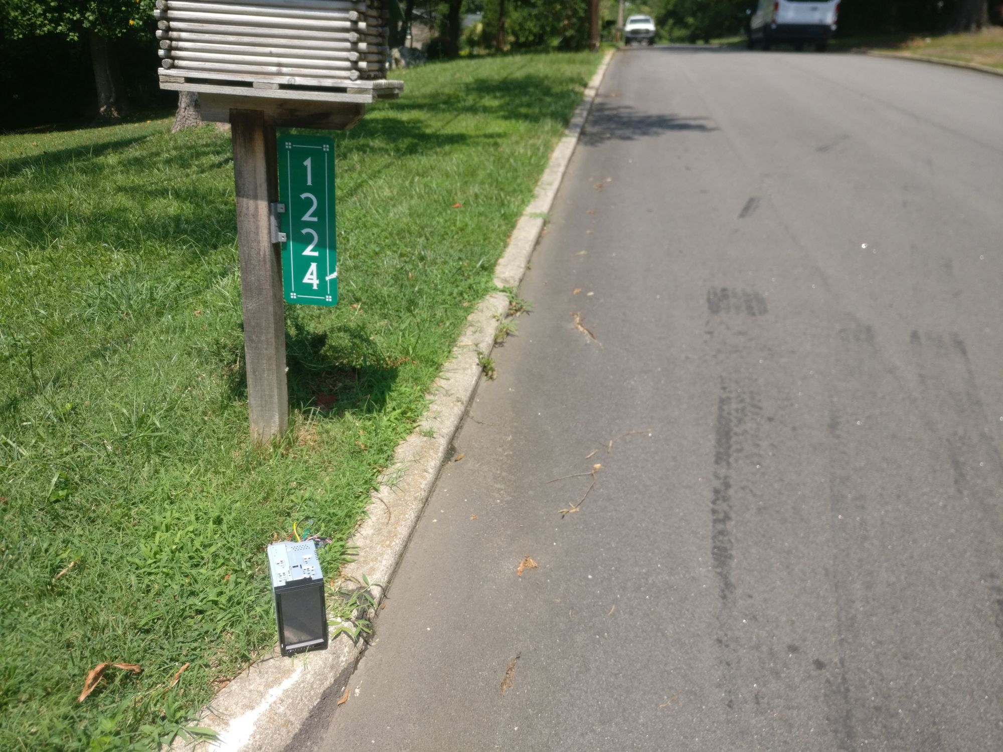
The old stereo head unit even found a good home (I assume) after I left it on the curb and some passerby picked it up.